THERMAL INSULATION METHODS FOR
HOUSING WITH REINFORCED CONCRETE STRUCTURE
Murat Aygün, Ph.D,
Hülya Kuş, Ph.D.
Division of Building Construction, Department of
Architecture
INTRODUCTION
Inadequate
or deficient application of thermal insulation gives rise to substantial
failures. Primarily, as a consequence of
excessive heat losses, energy is wasted and heating costs are increased
together with environmental pollution.
Almost all new-built housing in Turkey, whether low or high rise, is
constructed with an in-situ reinforced concrete structural frame and external
walls of lightweight masonry, either aerated concrete or fired clay hollow
blocks.
This
study is concerned with the effective use of thermal insulation in the category
of buildings described above, from the viewpoint of cold bridge avoidance. Alternatives of functional building elements
encountered most frequently in
The
constructional alternatives are subsequently compared in terms of performance
criteria such as condensation risk, heat storage capacity, and water
penetration. The position of thermal insulation and its relationships with
other components is explored in different floor, wall and roof configurations.
FUNCTIONAL ELEMENTS
The
alternatives of functional construction elements within the scope of this paper
are compared below in terms of performance criteria such as cold bridging, risk
of condensation, heat storage capacity and water penetration. Finally appropriate solutions are suggested
for each climatic region, based on both theoretical and experiential
knowledge.
1. Basements
1.1. Basements with
External Tanking
1.1.1. Basement without Insulation
Basements
can be conceived in a variety of ways. They
may cover whole of the plan area of a building or only a part of it. Depending on the slope and the levels between
the natural and filled ground some parts of the basement walls remain below and
some above the ground level. Also
depending on the type of use, the basement may be heated or not. These conditions have to be born in mind when
deciding on the method of insulation of basements.
1.1.2. Unheated Basements
In
this case the most effective position for the horizontal insulation is above
the ground floor slab where the latter can adjoin the external envelope, hence
be continuous and also allows floor heating.
Heat flow into the basement is therefore reduced along the
perimeter. The insulation material must
have adequate compressive strength to resist point loads. A less satisfactory position in terms of cold
bridging is below the ground floor slab.
If there is to be external insulation on the wall, then this must extend
below the ground frost level.
1.1.3. Heated Basements
In
the case of the basement required to be heated, the walls must be insulated,
preferably on the outside continuing up above ground level. The insulation material needs to be water-resistant
and sufficiently rigid to withstand lateral water and soil pressure. Additionally, insulation is also required to
be laid over the basement floor slab, especially in cold regions.
2. Floors
2.1. Ground Floors Resting on Soil
2.1.1.Uninsulated Floors
Heat
flow per unit area through floors to the ground is less than that through walls
to external air due to the heat storage capacity of ground. In mild climates there is no necessity for
complete floor insulation, which is omitted in practice anyway.

2.1.2. Floors with Perimeter Insulation
In
mild climates where the ground temperature does not fall too much, insulating
only either the outside or inside of edge beam may be adequate because of the
high heat storage capacity of soil. In
the outside position continuity of insulation over the exterior is achieved,
provided that the detail is compatible with that of above-ground wall
insulation. In the inside position there
are no detailing difficulties to overcome at the expense of discontinuity of
insulation.
2.1.3. Completely Insulated Floors
In
cold regions insulation should best be laid below the oversite slab to benefit
from its heat storage capacity. However,
if insulation is to be above, as in the case of floor heating then a vapour
barrier is required against condensation on the warm side of insulation.

2.2. Raised Ground Floors
2.2.1. Uninsulated Floors
Floors
may be raised above ground level for various reasons, such as topography,
architectural design or use of prefabricated components. In this case an air space is formed below the
slab and needs to be ventilated adequately through holes in the edge beam. Because of this requirement for ventilation
significant heat losses occur through the uninsulated floor.
2.2.2. Insulated Floors
Insulation
is most effectively placed over the floor slab to eliminate cold bridges, also
enabling floor heating to be installed.
If it lies below the slab then application difficulties are encountered
as well as heat losses through the perimeter.
2.2.3. Insulated Floors and Walls
The
same detail as above applies here, where the walls are externally
insulated.
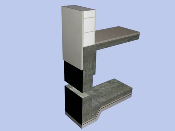
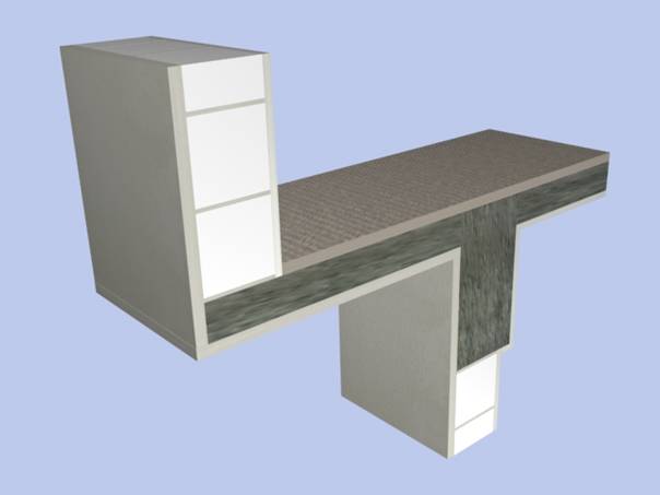
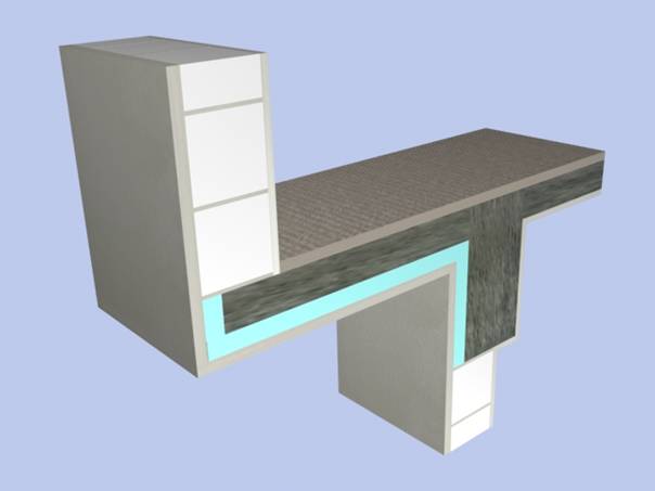
2.3. Cantilevered Upper Floors
2.3.1. Uninsulated Floors
The
upper floor slab may be projected outwards along all or part of the elevation
in order to increase the enclosed floor area.
The upper and lower external wall planes are thereby seperated. Since now a horizontal discontinuity of
insulation is inserted between the two wall planes, a cold bridge is
created.
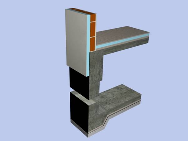
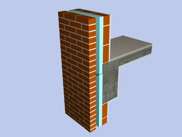
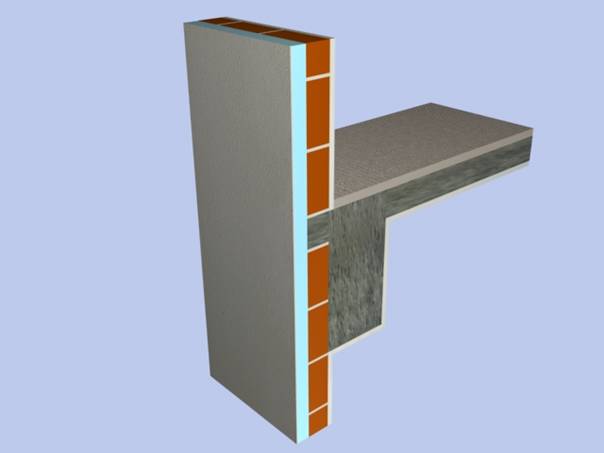
2.3.2. Floors with Insulated Soffit and Sides
Insulation
may be applied to the soffit and sides of cantilever to eliminate cold
bridging. External wall blocks can then
be laid so that they project by a certain amount beyond the slab edge to allow
insulating material to be positioned on the slab soffit and sides as well as on
the column external face. The thermal
resistance at these points can be similar to that of the wall. Expanded metal lath or equivalent material is
required over the joint between masonry and insulation to prevent cracks on the
external rendering.
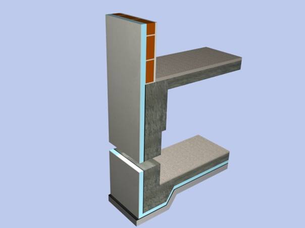
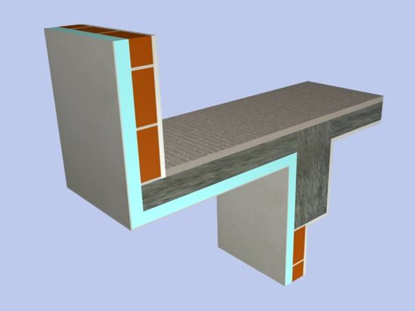
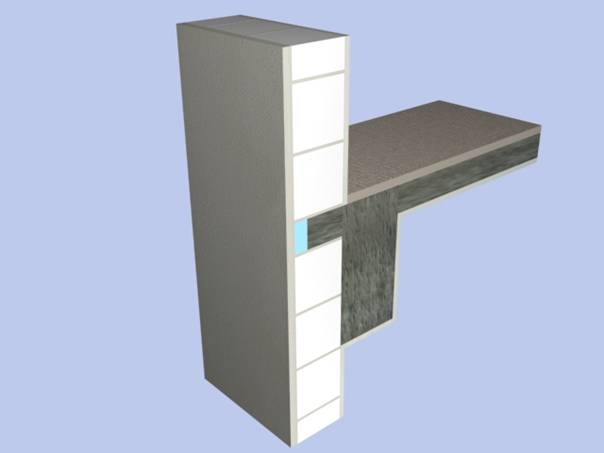
2.3.3. Floors with Complete External
Insulation
Insulation
is most effectively used when it is continuous over the walls (detailed in
3.1.3) as well as the cantilever soffit and sides. The soffit construction should be capable of
allowing internal moisture to escape by evaporation.
2.4. Balconies
2.4.1. Uninsulated Balconies
Significant
heat losses occur through balcony slabs.
They also present critical constructional problems in eliminating cold
bridges. Especially insufficiently
insolated balconies remain wet over long periods and give rise to greater heat
losses together with possible condensation.
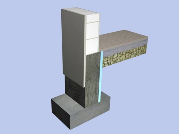
2.4.2. Simply Supported Balconies
Instead
of projecting the floor slab beyond the external wall, only the floor beams
perpendicular to the wall can be extended outwards supporting an in-situ or
precast one way span balcony slab. Hence
the area of cold-bridging is restricted only to the sectional area of the
projecting beams and the heat loss is reduced compared to that through a
cantilevered canopy.
2.4.3. Balconies with Specially Reinforced
Slabs
In
order to eliminate the cold bridge between the balcony and floor slabs, the
former can be cantilevered by special high-tensile steel reinforcement and the
gap inbetween filled with insulation.
This solution involves special care but enables the continuity of insulation
on the external wall.
3. External Walls
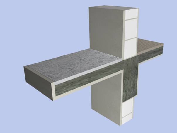
3.1. Infill Walls Between Columns
3.1.1. Unventilated Walls
3.1.1.1 Uninsulated Walls
In
reinforced concrete frame buildings, walls are mostly constructed on the edge
of the floor slab and between columns.
The wall material is chosen as either lightweight concrete or hollow
fired clay blocks. Then a rendering is
applied to the outside and a plastering inside.
Even though the wall thickness may provide sufficient thermal
resistance, the adjacent columns on either side and the floor slab at the top
and bottom surrounding the wall remain as cold bridges without any
supplementary measures.
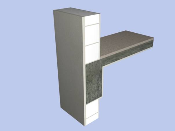
3.1.1.2 Walls with Insulated Columns and Beams
If
no additional insulating material is intended to be used on the walls then the wall
thickness may have to be increased nuch more than required for stability. However the surrounding column and slab faces
still require to be insulated with a suitable material. The joint between insulation and wall needs
to be covered with an expanded metal lath or similar material so that cracks
are avoided on the rendering over this joint between two dissimilar
materials. In order to obtain a flat
facade the wall must project beyond the edge of slab by a small amount
(30-50mm) to accommodate the thickness of insulation material. On slender walls (<150mm) the adverse
effect of this projection on stability has to be considered and possibly the
thickness increased.
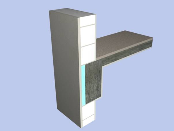
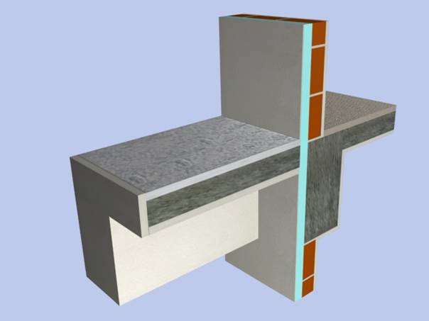
3.1.1.3 Walls with Complete External Insulation
This
method of wall insulation eliminates cold bridges effectively. Wall thickness is determined only with
respect to stability and is therefore reduced.
The heat storage capacity of wall material contributes to the thermal
performance of the wall and hence to the internal climate, decreasing the
energy consumption. The weight of wall
is less and the usable floor area more compared to a single layer wall. On the other hand this method involves
special details around openings, different trades and closer site
supervision.
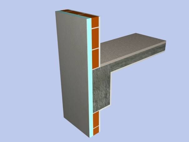
3.1.2. Insulated and Ventilated Walls
3.1.2.1 Cavity
Wall with Masonry Outer Leaf
In
humid regions, where rain penetration and condensation are more likely to
occur, this type of wall construction is suitable, especially on the north and
east facades. The outer leaf acts as a
weather shield. Gaps at the top and
bottom allow the cavity to be ventilated and drained, removing any moisture on
the insulation. Heat storage capacity of
the inner leaf also improves the thermal performance of the wall. However this multi-layer construction
necessitates some accessories such as cavity ties, support angles, cavity trays
and requires high quality of workmanship.
3.1.2.2 Cavity
Wall with Lightweight Cladding
This
type displays a similar physical performance to that of 3.1.4.1. A light-weight carrier frame is fixed to the
masonry behind. Subsequently insulation
is inserted between the frame members to which external cladding is fixed. An air cavity is left between insulation and
cladding. Compared to the wall with
masonry outer leaf described above, the weigttt is less and total thickness
smaller.
3.1.2.3 Cavity
Wall with Insulated Lightweight Cladding
In
hot regions the cladding may be insulated to prevent overheating of the wall. The air cavity provides cooling by convection
and wind. This type is particularly
effective on south and west facades.
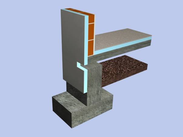
3.2. Infill Walls on the Outside of Columns
3.2.1. Uninsulated Walls
Cold
bridges along columns, as illustrated in 3.1.1., can be avoided if the floor
slab or a shallow edge beam is projected beyond the outer face of columns and
the external wall is supported by this cantilever. In such a situation only the face of the
floor slab or the edge beam creates a cold bridge. However rigidity of the wall construction Is
reduced because the walls are not restrained by columns. Therefore ties are
required to attach the walls to the columns.
Additionally, since walls are continuous in the horizontal direction,
vertical movement joints should be left at certain distances. Another drawback of this solution compared to
3.1.1. is that the external columns are not contained within the wall
thickness, resulting in some loss of usable floor area.

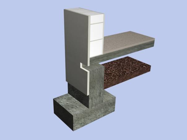
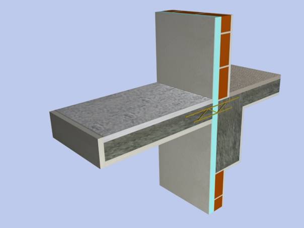
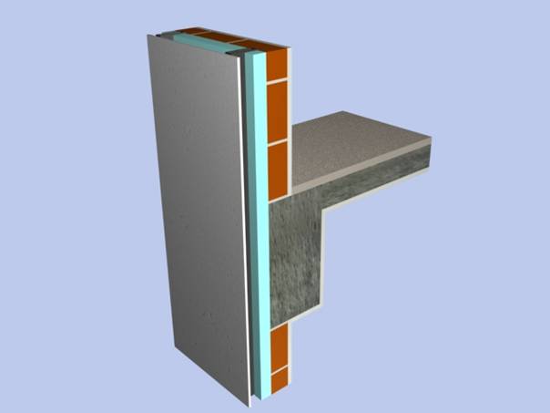
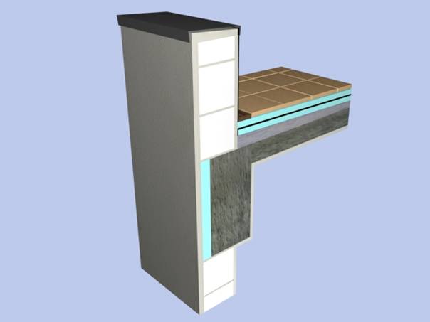
3.2.2. Walls with Insulated Outer Face of
Floor Slab
The
outer face of horizontal structural elements can be insulated to overcome
cold-bridging. In this case the wall is
brought forward of the slab edge by the same amount as insulation thickness.
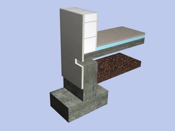
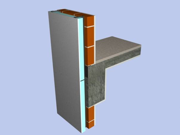
3.2.3. Walls with Complete External
Insulation
This
detail is a superimposition of 3.1.3. and 3.2.2., each one of which, in actual
fact, is quite adequate on its own and can only be cost-effective in extremely
cold regions or where a very uniform surface temperature distribution is
required inside.
4. Roofs
4.1. Sloping Roofs
In
these roofs, if heat and sound insulation is placed on the sloping surface, the
area to be insulated is greater than that of the flat roof because of its geometric
properties.
4.1.1 Roofs with
Rafters
4.1.1.1
Roofs with Thermal Insulation on Slab
In
this solution, also known as “cold roof”, the heat insulation is placed over
the roof slab and the attic space remains cold.
There should be ventilation provided along the eaves and ridge. As the slope decreases, an increase in the
ventilation opening is required. There
is an application ease in this option.
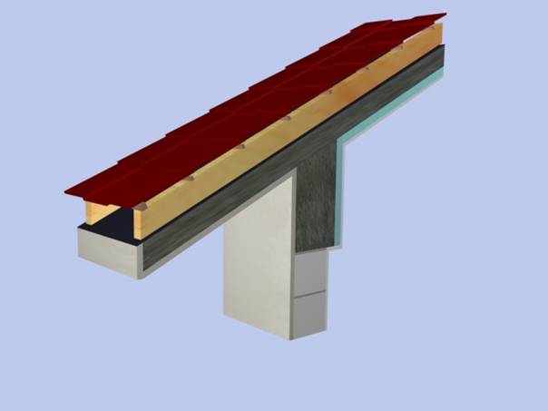
4.1.1.2 Roofs with Thermal
Insulation between or under Rafters
In
both cases ventilation is required in any gap between the rafters. If the insulation is placed between the
rafters, the thickness of the roof is decreased. The distance between the rafters should be
suitable for the insulation pannel’s dimensions to fill the openings
completely. There should be at least 5cm
gap between the rafter’s top edge and the insulation layer.

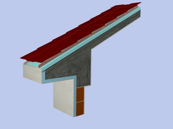
4.1.1.3 Roofs with Thermal
Insulation over Rafters
Thermal
insulation and waterproofing layer above are laid over rafters continuously. Gaps along battens would be helpful for
drainage of water leaking between tiles or additional counter-battens can be
used for drainage. In cases of a high
risk of condensation a vapour barrier is used on the inner surface of heat
insulation.
4.1.2. Roofs with
Slab
Rafters
are sustituted by a concrete slab to form the roof plane.
4.1.2.1
Roofs with External Thermal Insulation
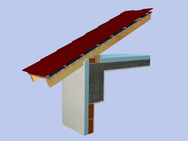
4.1.2.1.1 Roofs without Ventilation
The
heat bridges could be blocked if the heat insulation over the sloped slab also
covers the eaves. A narrow eaves is more
rational in this option. The heat
storing capacitiy of the slab reduces the load of space heating. The application of the roof finish should be
carried out without damaging the waterproof layer or impermeable seals should
be used.
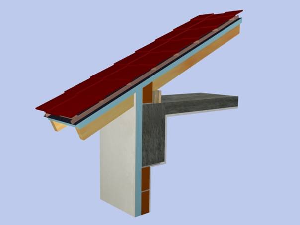
4.1.2.1.2 Roofs with Ventilation
By
evaluating the solution before, a ventilation layer can be composed by the help
of laths that is placed parallel to the slope.
The drainage of water that is leaked from the coating or the vapour
reached from the inner volume is procured with this ventilation layer. Building a narrow eaves or building it with
metal suffixes would be useful for the application.
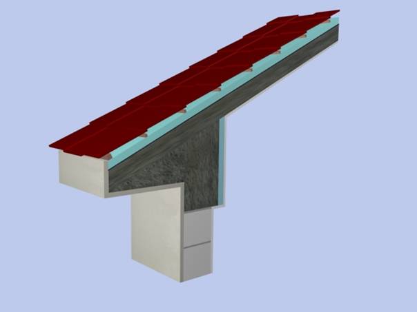
4.1.2.2 Roof with Internal Thermal Insulation
(Ventilated or Non-ventilated)
The
heat insulation could be placed on the inner surface of the roof slab for heating
the inner space in a shorter time and obviating the need to insulate around
wide eaves. Ventilation and water
drainage is achieved between the rafters on the slab, and roof finish placed
over those rafters. This application
calls for a finish and vapour barrier on the inner surface.
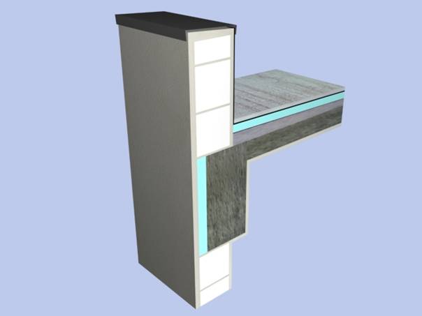
4.2 Flat Roofs
4.2.1
Warm Roofs (Ventilated or Non-ventilated)
In
the case of using an open cellular heat insulation material, this should be
covered by a waterproofing membrane resistant to sunlight effects, with a
vapour barrier underneath. The vapour
barrier may not be needed if ventilation is possible over the heat
insulation. A sufficient thickness of the parapet can prevent heat
bridging in this option.
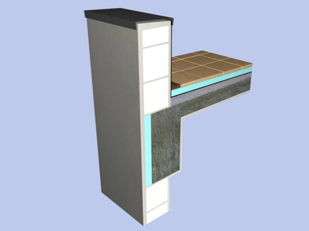
4.2.2 Inverted Roofs
Closed-cell
extruded polystrenes makes placement of the heat insulation over the
waterproofing membrane possible which is thus protected during the construction
period and allows foot traffic over the roof.
Moisture condensation is prevented without using a vapour barrier. Heat insulation panels should be thicker than
those for sloping roofs as the latter are allowed to get wet.
4.2.3 Advanced Inverted Roofs
By
developing the previous solution further, the total thickness of the heat
insulation can be smaller. This option may be more viable for
applications over the existing waterproofing layer.
Reference