Homework 4
Hand in your homeworks both in hard copy form and on 3.5" disk with the label of your name and number.
Due on Wednesday, May 1 2002.
|
030000008 |
| 030000010 |
| 030000011 |
| 030000013 |
| 030000024 |
Given:
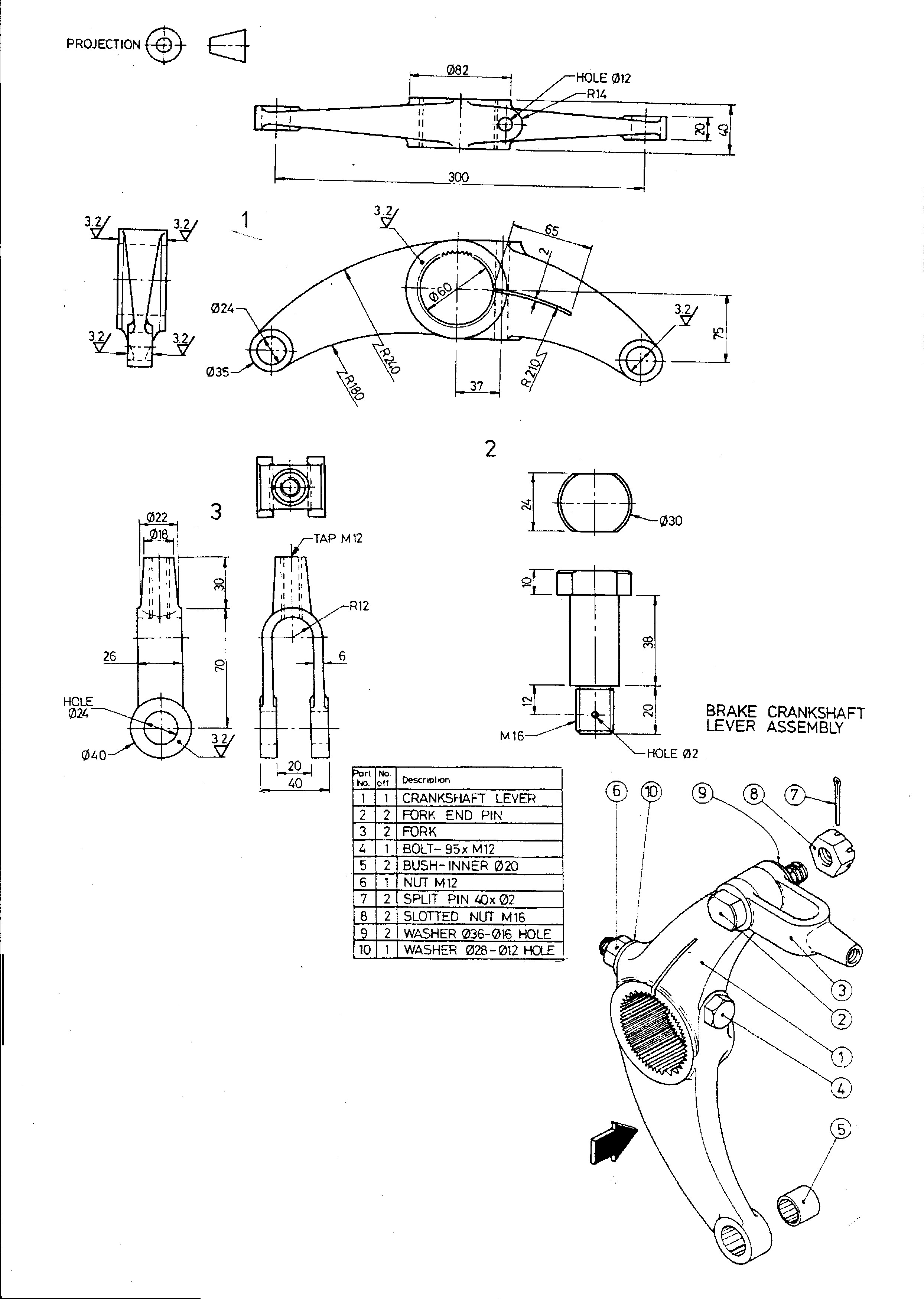
The pictorial drawing of a partly assembled BRAKE CRANKSHAFT from a lorry breaking sistem is given.
Details of some parts of the assembly are shown.
Required:
Draw the front view.
Draw a sectional end view with the section plane cutting through the two fork end.
Optional:
Creat 3-D model
| 030000029 |
| 030000037 |
| 030000040 |
| 030000045 |
| 030000051 |
Given:
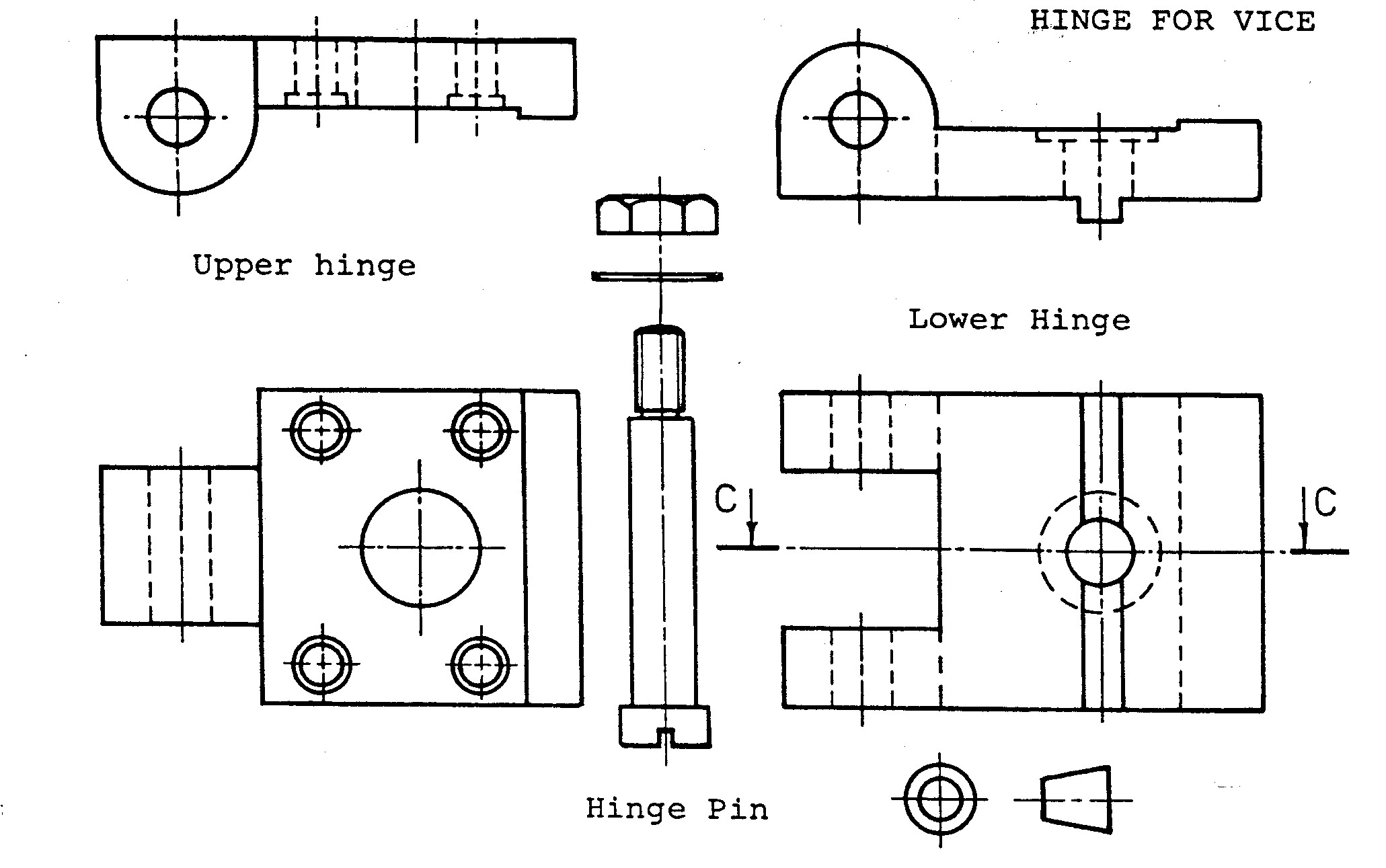
Details of the parts of the assembly are shown. (Hinge for vice)
Required:
Draw a sectional assembly drawing of the component parts looking on the cutting plane CC
and positioning each part..
Draw a top view .
Optional:
Creat 3-D model
| 030000059 |
| 030000069 |
| 030000108 |
| 030990050 |
| 030990092 |
| 030990097 |
| 030990212 |
| 030000113 |
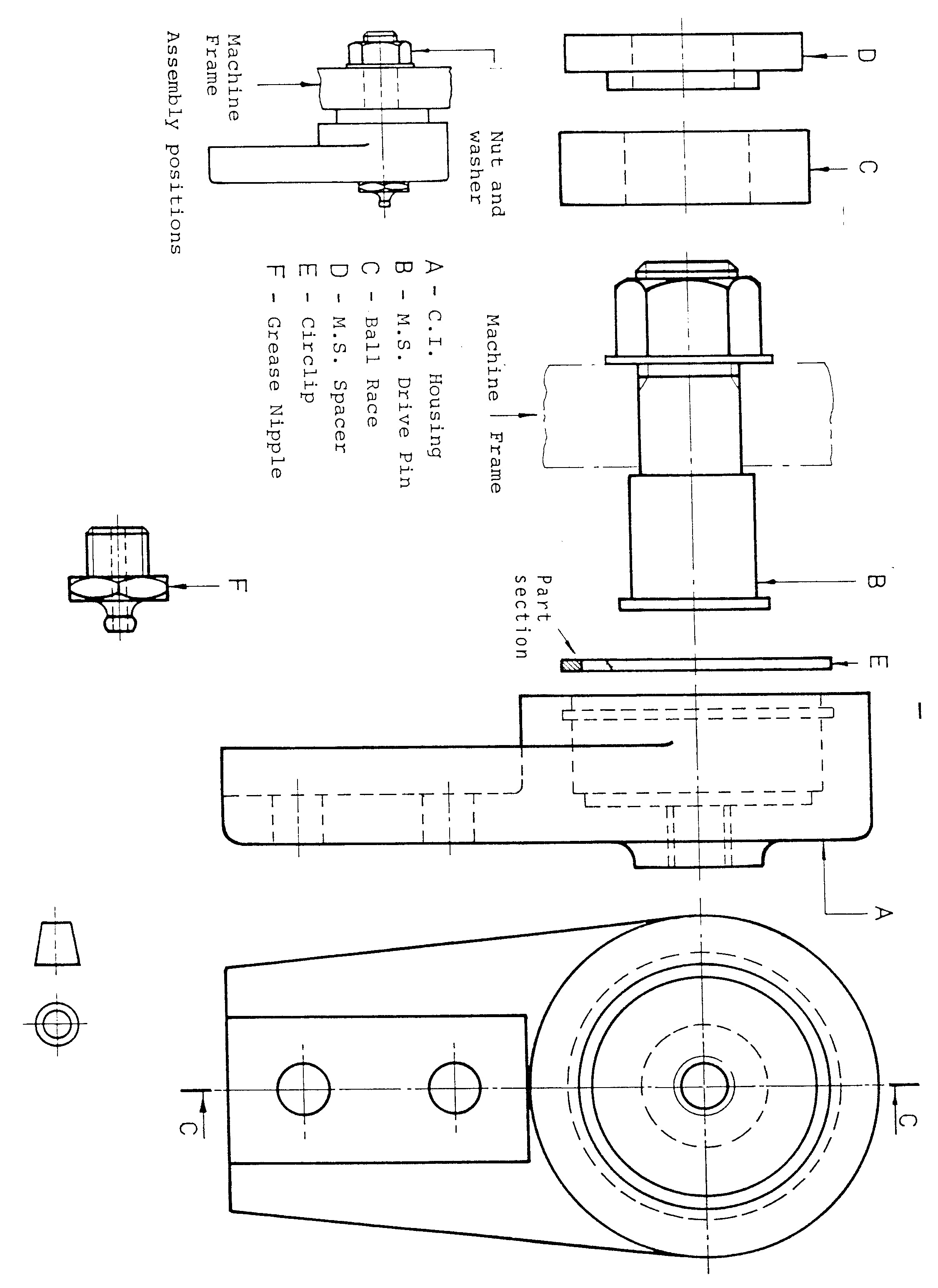
Given:
Details of the parts of the assembly are shown (Anti-vibration mounting).
Required:
Draw a sectional assembly drawing of the component parts looking on the cutting plane CC
and positioning each part.
Draw a top view .
Optional:
Creat 3-D model

| 030000119 |
| 030000120 |
| 030000142 |
| 030000159 |
| 030010007 |
Given:
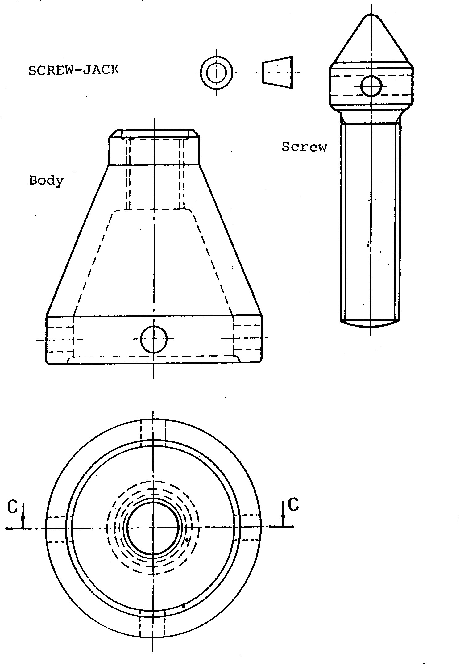
Details of the parts of the assembly are shown (Screw-Jack).
Required:
Draw a sectional assembly drawing of the component parts looking on the cutting plane CC
and correctly positioning each part.
Draw a top view .
Optional:
Creat 3-D model
| 030010017 |
| 030010020 |
| 030010021 |
| 030010026 |
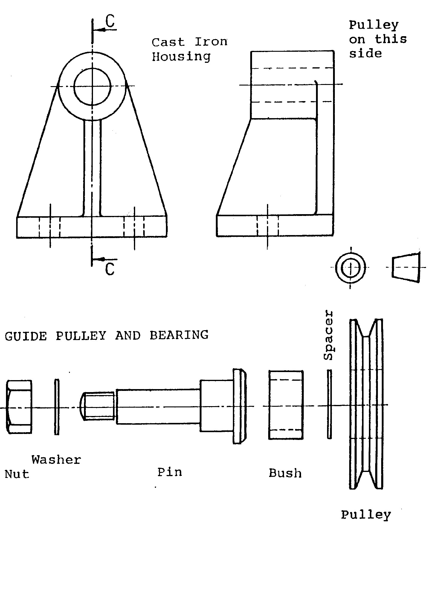
Given:
Details of the parts of the assembly are shown (GUIDE PULLEY AND BEARING).
Required:
Draw a sectional assembly drawing of the component parts looking on the cutting plane CC
and correctly positioning each part.
Draw a top view .
Optional:
Creat 3-D model
| 030010027 |
| 030010031 |
| 030010075 |
| 030010078 |
| 030010080 |
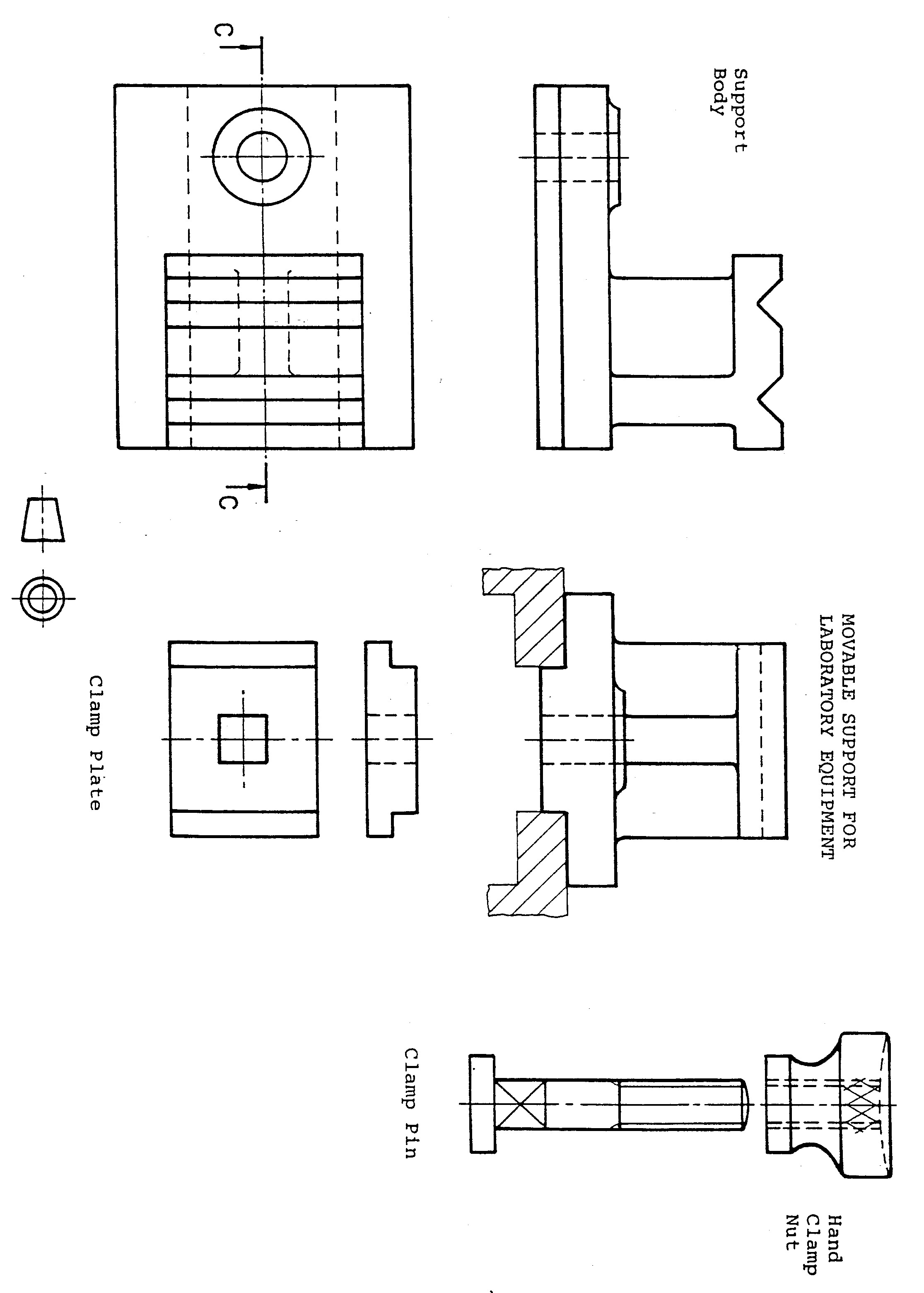
Given:
Details of the parts of the assembly are shown (MOVABLE SUPPORT FOR LABORATORY
EQUIPMENT).
Required:
Draw a sectional assembly drawing of the component parts looking on the cutting plane CC
and positioning each part..
Draw a top view .
Optional:
Creat 3-D model
| 030010092 |
| 030010099 |
| 030010101 |
| 030010105 |
| 030010702 |
| 030010703 |
| 030010801 |
| 030980088 |
| 030990048 |
| 030010115 |
Given:
Details of the parts of the assembly are shown .
Required:
Draw a sectional assembly drawing of the component parts looking on the cutting plane CC
and positioning each part..
Draw a top view .
Optional:
Creat 3-D model
| 030010136 |
| 030010138 |
| 030010141 |
| 030010142 |
| 030010145 |
| 030010162 |
| 030010164 |
| 030010701 |
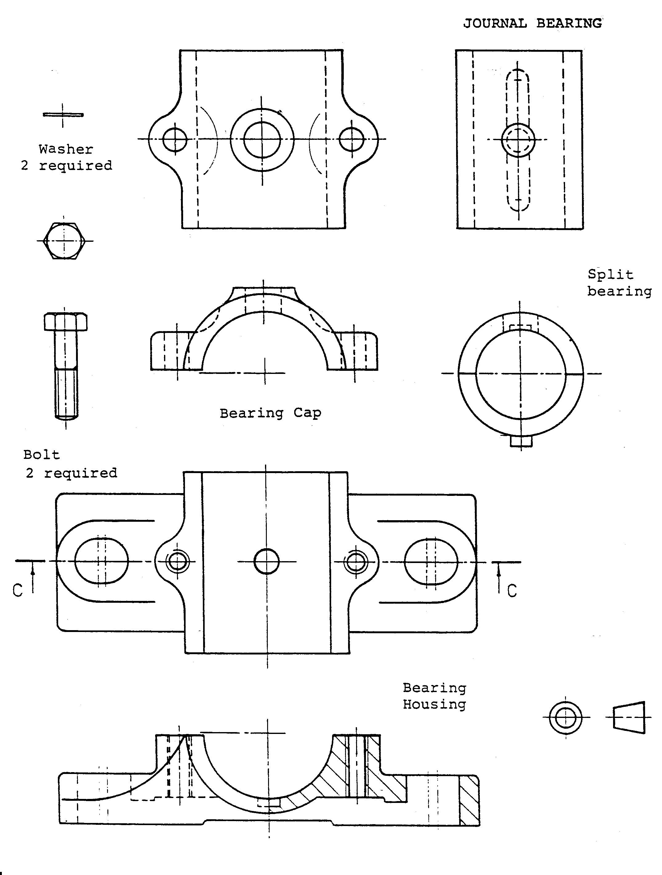
Given:
Details of the parts of the assembly are shown (JOURNAL BEARING).
Required:
Draw a sectional assembly drawing of the component parts looking on the cutting plane CC
and positioning each part.
Draw a top view .
Optional:
Creat 3-D model