IR stands
for Instrument Rating and is our abilitation to operate
without visual reference (mandatory for airline operations).
Here are a few tips concerning it.
Index
Interception:
· 90° radial change
· 30°/40° radial change
Racetracks:
· How to - use a VOR/HSI/ADF!
Useful formulae:
·abbreviations
·simplified
formulae
·rapid join
·DME arc
·racetrack
Snowtam decoder:
· notam format
· metar format
Changing radial using 90° interception
1. Introduction
Changing radial using 90° interception is an exercise used at the beginning of IFR training in the aim of:
· Understanding the visualization of radials
· Learning to manage time and the chronological sequence of the calculations/
2. Objective
Mentally project the flight path, calculate the anticipation required in order to finish on the desired radial.
3. Reminders
Anticipation with an interception angle of 90°:
· 20/T'= A° (no wind).
Reminder on cosine in order to:
· Determine the moment where the deviation in flight path should begin.
· Know the distance from the station when the deviation in flight path has finished.
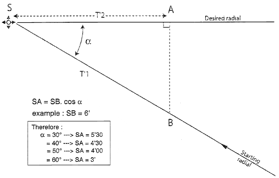
With the turn:
4. Description
4.1 General method:
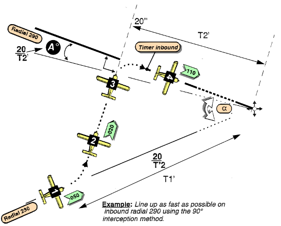
· Changing radial using the 90° interception method where the angular difference between the two radials is 30° to 60°.
· Intercepting the desired radial at 90°.
Example:
· The aircraft is on radial 230
· The radial to intercept is inbound radial 290
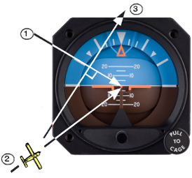
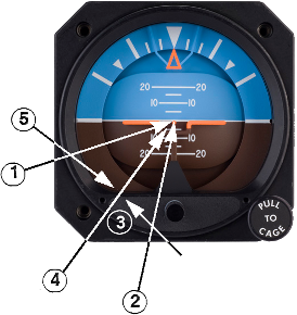
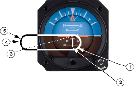
- Visualizing the example on the ADI
1. Visualize the radial to be intercepted
2. Visualize the current radial
3. Visualize the turn direction and the approximate TRK (m) (010 - 020)
4.2 In practice:
1-> Visualization
and projection onto ADI
2-> Direction of turn
3-> TRK (m) / HDG (m)
4-> When established on heading: set the navigation instrument for the
desired track and crosscheck
5-> Calculate T2 and the anticipation 20/T2'
6-> Add the effect of wind during the turn to the anticipation
7-> Calculate the next HDG (m)
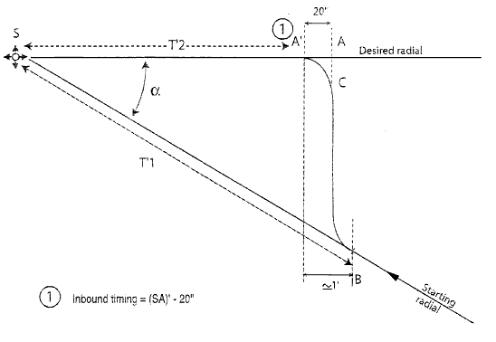
8-> At the end of the intercepting turn and with wings level: start inbound
timing using T2'-20" (no wind)
5. Key Points
_Visualization of the exercise
_Organisation of the workload:
· HDG (m) for 90° interception
· Anticipation
· Next HDG
· Estimate the inbound time
6. Common errors
· Poor mental projection
· Forgetting the wind
· Forgetting the anticipation
· Rate one turn not expected
· HSI error: setting the course index 180° in the opposite direction. Turning the wrong way.
Change of radial: 30°/40° Method
1. Introduction
30°/40° radial changes are aimed at optimising the flight path time for a procedure (required by pilot or ATC).
2.
Objective
To be able to line up quickly on a reference radial while approaching overhead
station.
3. Description
Overview: (angular difference of 20° to 60°)
1. Visualise where the aircraft is going
2. Visualise current position
3. Turn direction and calculation of magnetic track
4. Visualise the next radial 10° further along
5. Calculate next heading (if left turn then closing turn will be to the right and vice versa...)
Example:
Aircraft is currently on inbound
radial 180, intercept inbound radial 240. Call out: "INTERCEPT INBOUND
RADIAL USING 30°/40° METHOD".
Left turn to approximate heading of 330°.
Detailed description:
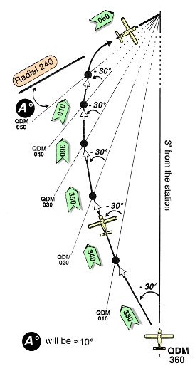 30°/40°
METHOD (for an optimum flight path in terms of time at
three minutes before the station)
30°/40°
METHOD (for an optimum flight path in terms of time at
three minutes before the station)
IF OPENING TURN INTO THE WIND
δ=X, 2/3 X, X/3
The calculation should be made on crossing each radial.
Key Points:
· Visualisation
· Direction of opening turn
· Heading stable, calculation of next track
· For δ use X, 2/3 X, X/3
· Integrate the wind factor throughout the manoeuvre and joining turn towards the desired track.
Common Errors:
· Bad visualisation
· Same calculation used for next radial
· Direction change too soon/late
· Drift calculation too long
· Bad anticipation, at the end of the exercise the 10° value is often incorrect due to wind
· Remember safety altitude which may vary during the radial change procedure.
Racetracks
1. Introduction
· Racetracks are flight paths specified on approach charts and are used to position the aircraft on the approach track.
· Holding patterns are used to make an aircraft wait before approach.
2. Objective
To know how to visualize the holding pattern or racetrack, determine the entry type and verify the aircraft position in order to exit on the correct track.
3. Detailed Description
Racetrack or holding pattern requirements:
1. A fix (beacon, radial intersection, DME distance).
2. An inbound track
3. A turn direction (the standard turn is to the right).
4. An outbound time or a defined fix (distance, beacon or radial).
5. A second turn (procedure turn for a racetrack).
Note: All turns should be made at rate one (except for correction of overshoot or undershoot).
Example:
Call-out: "RACETRACK OR HOLDING PATTERN ON INBOUND RADIAL 270, RIGHT TURN,
OUTBOUND TIME 1 MINUTE".
- Visualizing the example on the ADI
1. Visualize where the aircraft is going
2. Visualize where the aircraft is
3. Direction of turn and magnetic heading
Execution and verification of racetrack or holding pattern:
Know how
to calculate rapidly (3 radials, the
"skeleton" of the racetrack)
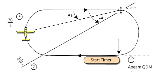
Aa: Anticipation angle
Ca: Check angle
1. Abeam QDM: is perpendicular to the track (using the needle arrowhead)
2. Check radial (Cr): calculation method 40/T (with the tail of the needle)
|
Outbound Time |
1' |
1'30' |
2'00 |
2'30 |
3'00 |
|
Ca |
40° |
25° |
20° |
15° |
10° |
|
Aa |
20° |
12° |
10° |
5° |
5° |
3. Position verification radial calculated using the 20/T method
o Verified using the parallel magnetic track
o Verified using the needle arrowhead.
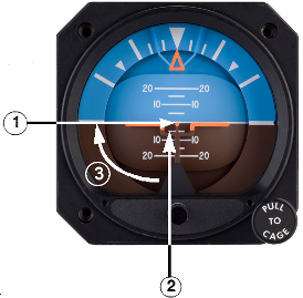
- Visualizing further the example on the ADI
Racetrack
on inbound radial 270, right turn, outbound time 1 minute (no
wind).
Method without wind:
1. Aircraft stabilize on heading: start timer
2. If the abeam point has not been passed: re-start timer when passing abeam QDM
3. Interception of position check radial (Cr)
4. Once at the perpendicular heading, verify position using 20/T
5. 30° before final heading, make a final verification
Using the ADI scheme:
1. **none**
2. Abeam QDM: QDM 360°
3. Check radial (Cr): 270 - 40 = 230
4. QDM 20/T is 090 - 20 = 70
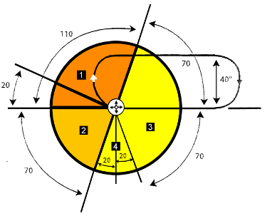 Four
entry sectors are defined and each sector has an associated flight path.
Four
entry sectors are defined and each sector has an associated flight path.
The manoeuvre begins when the aircraft passes overhead the holding fix.
· SECTOR 1 = Parallel entry
· SECTOR 2 = Offset entry
· SECTOR 3 = Direct entry
· SECTOR 4 = Special 90° entry
Note: Sectors
1 - 2 and 3 are ICAO recommendations.
Sector 4 is a special procedure used by the operator (France only)
Parallel Entry:
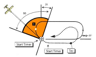
When overhead the fix, start the timer and turn to take the reciprocal magnetic
track to the inbound track for the racetrack of holding pattern and maintain
this heading for:
Te =
· 1 min if tailwind or no wind
· 1 min 30 seconds if headwind
Turn at 25° of bank in the opposite direction to the flight path specified in order to join the inbound track.
Note:
Te = Outbound time
Tec = Corrected outbound time
Offset Entry:
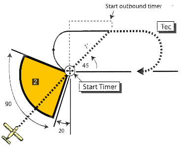
When overhead the fix, start timer and set the heading which will allow a
flight path to be followed for one minute which is at an angle of 45° to
the inbound track on the racetrack or holding pattern side, then follow the parallel
track for the planned time or for the specified time minus one minute.
With wind: the opening 45° turn will be modified by the drift δ of the racetrack or holding pattern track.
Time correction:
· if heading away from the crosswind then correct using 1'-δ" for the track
· if heading into the crosswind then correct using 2δ" for the track.
Direct Entry:
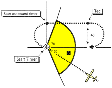
When overhead fix, start timer to carry out a turn in the specified direction
in order to follow the outbound track for the planned time (holding
pattern) or for an imposed distance (racetrack
procedure) then turn in the specified direction to line up on the
inbound track.
Special 90° Entry:
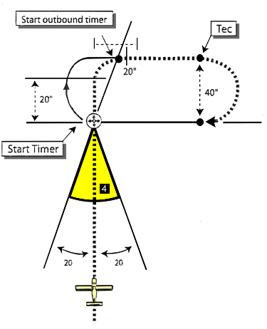
When the aircraft arrives in the 40° sector defined on the scheme on your
right, the alteration of heading will be so large in direct entry that the
quality of the outbound leg will be compromised by the reduction in the turn
diameter.
A special 90° (direct) entry has been defined.
When overhead fix, start timer and follow a track perpendicular to the specified inbound track for 20 seconds. Turn in the specified direction to follow the outbound magnetic track for the planned time of 20 seconds (holding pattern procedure or for the imposed distance (racetrack procedure), then turn to line up on the inbound track.
4. Key Points
Organisation of workload:
· visualization of position
· Turn direction for holding or racetrack pattern
· Magnetic track/magnetic heading
· Calculation of abeam QDM
· Calculation of check radial (Cr) 40/T
· Calculation of anticipation radial 20/T
· Calculation of magnetic heading with alignment on track if necessary
5. Common Errors
· Bad visualization of position --> causes wrong entry type to be used
· Slow calculations
· Not respecting the verifications (abeam, lead radial)
· Forgetting the 1st or 2nd turn will be into the wind
· No verifications during 2nd turn
|
Control |
Function |
|
|
Mouse |
Click/Drag on the Map |
Move the airplane, the transmitters, or change the wind vector (if in wind mode) |
|
Click the Buttons |
Change the vector (OBS) for the instrument (except the RMI, DG) |
|
|
Keyboard |
Up & Down Arrows |
Increase or decrease the airplane |
|
Left and Right Arrows |
Increase or decrease turn rate (deg/sec) |
|
|
Space Bar |
Instantly set the turn rate to zero |
|
|
Enter |
Reposition transmitters to original positions - |
|
|
R |
Toggle radials on & off (dark colors = from side of VORs, light colors = TO side of VORs) |
|
|
1 or 2 |
Switch instrument 1 or 2 between VOR, HSI, ADF, |
|
|
W |
Toggle Wind mode (shown in status line) - when in wind mode you can click/drag on the map to change the wind vector |
|
|
P |
Pause the animation (wind and
airplane motion) - you |
|
|
T |
Trace - start/stop a trail of dots showing the airplane's path |
|
|
H |
Hide - stop/start displaying the airplane and trace |
|
|
L |
Lost - randomly reposition the airplane on the map - most useful when the plane is hidden |
|
source: Tim B. Carlson
Abbreviations
|
Aa |
Anticipation angle |
|
Bf |
Base factor |
|
BRG |
Bearing |
|
Ca |
Check angle (for racetracks) |
|
Cr |
Check radial >(for racetracks) |
|
D |
Distance |
|
δ |
Drift |
|
HDG(m) |
Magnetic heading |
|
T |
time |
|
te |
Outbound time |
|
tec |
Corrected outbound time |
|
TRK(m) |
Magnetic track |
|
Ve |
Effective Wind |
|
Vt |
Crosswind component |
|
Vw |
wind (general) |
|
X |
Maximum drift |
|
Bf = 60/TAS |
|
TAS/ |
80 kt |
100 kt |
120 |
150 kt |
180 kt |
200 kt |
|
Bf |
0,75 |
0,6 |
0,5 |
0,4 |
1/3 |
0,3 |
|
NM/min |
1,3 |
1,6 |
2 |
2,5 |
3 |
3,3 |
Ve =
Groundspeed - TAS
Vt = δ x TAS (NM/min)
X = Vw . Bf
|
Wind angle |
Drift δ |
Ve* |
|
0° to 30° |
X/3 |
Vw |
|
30° to 60° |
2/3 X |
2/3 Vw |
|
60° to 90° |
X |
Vw/3 |
*Note: simplified calculation where no GPS or DME is available
TAS = IAS + 1% per 600 feet of altitude ± 1% for every 5% C difference from ISA
Note:
· Hotter --> "+"
· Colder --> "-"
Anticipation
|
Interception |
120° |
90° |
60° |
30° |
|
|
30/T |
20/T |
10/T |
2/T |
te = 100 -
α
tec (headwind) = (100 - α) + 2
Ve
tec (tailwind) = 100 - α
DME Arc
· Anticipation: D (NM) = Groundspeed/200
· Anticipation for final approach interception: A° = TAS/3D or 20/T
Racetrack (check radial and
anticipation angle)
|
Outbound time T |
1' |
1'30 |
2'00 |
2'30 |
3'00 |
|
Ca* |
40° |
25° |
20° |
15° |
10° |
|
Aa* |
20° |
12° |
10° |
5° |
5° |
· *Ca = Check angle
· *Aa = Anticipation angle
|
Entry type |
Outbound
time |
Inbound
time |
|
20/T |
|
Direct |
Headwind: |
Headwind Vw = T + 1/2.Ve for every minute of T |
With headwind component: |
+ 50% or 30/T with tailwind |
|
Perpendicular |
Headwind: |
With headwind component: |
||
|
Offset |
Headwind: |
With headwind component: |


NOTE:
· The product of (T-Ve) and (T+1) Ve is in seconds
· Ve, δ and δ sec on racetrack axis
· *if 3δ sec or 20 sec + 3δ sec > 30 sec then correct for drift
|
SNOWTAM DECODER - Notam Format |
|||||||||||||||||||||
|
AERODROME |
A |
||||||||||||||||||||
|
DATE/TIME OF OBSERVATION |
B |
B |
B |
||||||||||||||||||
|
RUNWAY DESIGNATORS |
C |
C |
C |
||||||||||||||||||
|
CLEARED RUNWAY LENGTH (meters) |
D |
D |
D |
||||||||||||||||||
|
CLEARED RUNWAY WIDTH (meters) |
E |
E |
E |
||||||||||||||||||
|
DEPOSITS OVER TOTAL RUNWAY LENGTH 1. DAMP 2. WET or water patches 3. RIME OR FROST COVERED (depth less than 1 mm) 4. DRY SNOW 5. WET SNOW 6. SLUSH 7. ICE 8. COMPACTED OR ROLLED SNOW 9. FROZEN RUTS OR RIDGES |
F |
F |
F |
||||||||||||||||||
|
MEAN DEPTH (mm) |
G |
G |
G |
||||||||||||||||||
|
BRAKING ACTION on each third of
RWY |
H |
H |
H |
||||||||||||||||||
|
MEASURED OR CALCULATED COEFFICIENT
·
When quoting a measured coefficient use the observed two
figures, · When quoting an estimate use single digits) |
|||||||||||||||||||||
|
CRITICAL SNOWBANKS |
J |
J |
J |
||||||||||||||||||
|
RUNWAY LIGHTS |
K |
K |
K |
||||||||||||||||||
|
FURTHER CLEARANCE |
L |
L |
|||||||||||||||||||
|
FURTHER CLEARANCE EXPECTED TO BE COMPLETED BY... (GMT) |
M |
M |
|||||||||||||||||||
|
TAXIWAY |
N |
N |
N |
||||||||||||||||||
|
TAXIWAY SNOWBANKS |
P |
P |
P |
||||||||||||||||||
|
APRON |
R |
||||||||||||||||||||
|
NEXT PLANNED OBSERVATION/MEASUREMENT IS FOR... |
S |
||||||||||||||||||||
|
PLAIN LANGUAGE REMARKS |
T |
||||||||||||||||||||
source: Sir Pat BOONE, Captain B737-B767 from www.b737mrg.net